 If you own or are thinking about getting a hotspot for DMR or any other mode, I think you will find this information very useful. Many hot spots come with a tiny (about 1" or 1.5cm) screen but likely this is very hard to read and of course, does not display nearly enough information as it could. So here comes an inexpensive upgrade. Nextion screens come in various sizes. I decided to use a 4" screen to give me more information using software on the screen itself to handle additional data piped from the RaspberryPi. And it does this with ONLY 4 wires, 2 of which are power.
Active User List
Last Heard List
Above is what you will end up with, or something similar. There are many pre-packaged screen files to load via the SD card slot into the Nextion screen. This is a very simple process and you can experiment with what your preference for the display is easily after building it. This is relatively easy, just pay attention to the screen size. I also installed a power switch on the front so I can turn it on and off without having to remove the USB power cord all the time.
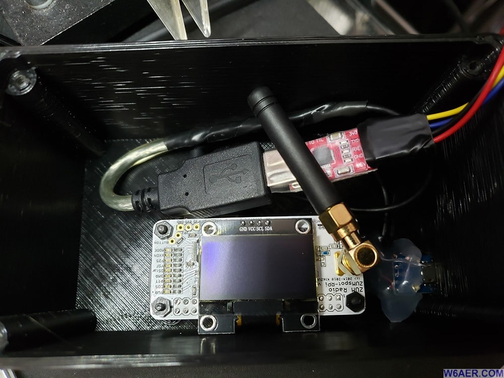
Let's stary with the insides. In this build (I had several) I used the ZUM spot with a RaspberryPi Zero for a base. The USB cable is connected to a serial converter to feed the Nextion Screen. Note the SMA right angle adapter I had to get to make it all fit in the box properly.
NOTE:You will need to change the screen settings in the PiStar software to display type Nextion. The Port to /dev/ttyUSB0 and for the Layout is ON7LDS L3 which works nicely. These may vary depending on your setup and Nextion image you use.
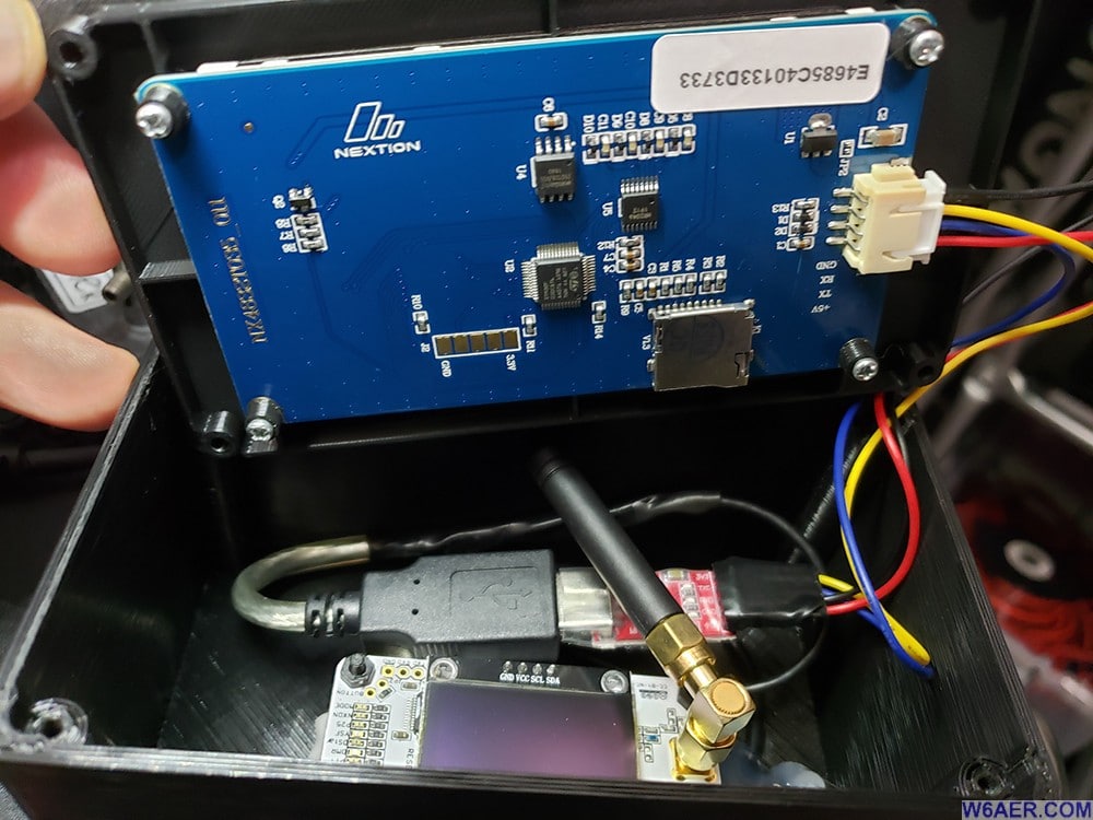
Here is it exposed. The blue board is the back of the Nextion, fits together nicely! The case by the way is 3D printed and is widely available online as well.
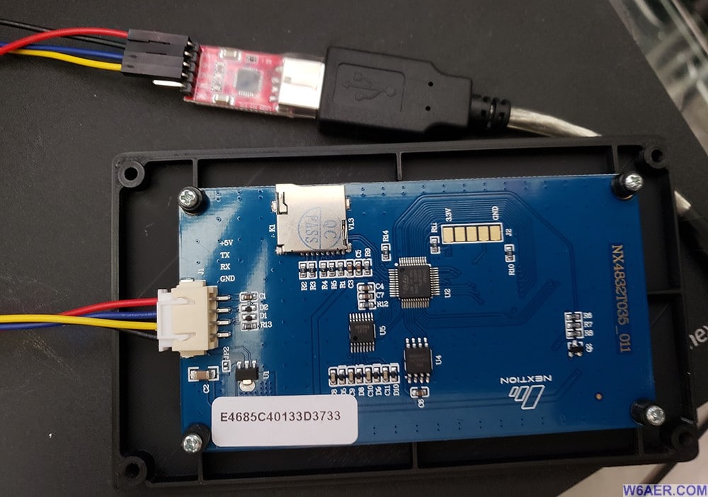
Note the cable order, it is NOT 1 to 1, Red and Black are power, Blue and Yellow are DATA in and out. The red board is the converter I got online for a few dollars, many versions out there, they all work well.
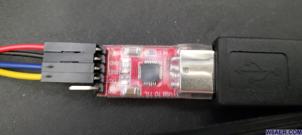
Here is a close-up of the connections, not the extra unused pin. Not needed in this case, but your model may vary. This unit is also wrapped in clear insulation, which I really like.
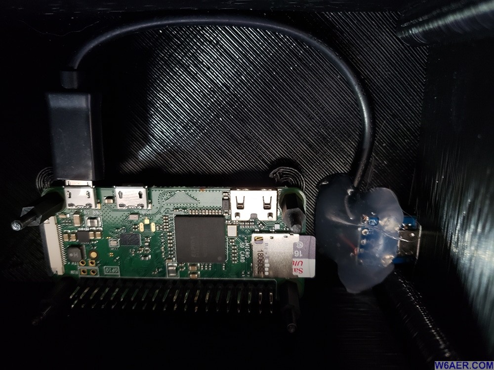
Here is another view of another build showing just the RaspberryPi ZERO board. The hot glue just holds the jack in place. The same idea, I removed the MMDVM to show how it should be looking.
Top Sides
Back Sides
Fors those curious or building their own, above are two views of the kits needed to make this all work and on which you can build on and add a Nextion screen if you want to do so.
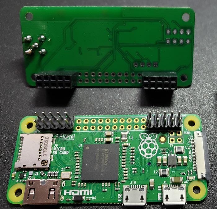
Lastly, this picture above shows how the units fit together. Sometimes you will need to solder on the pins yourself. Not a big deal and usually they do include all the parts needed.
I hope you give this a shot and if you build it, send me some photos. I would love to see what others come up with.


