I got really interested in this project after reading about it online and before obtaining my hexbeam. It was a great learning experience, despite the fact that I decided not to keep it. I assume you know what these are already if you are reading this.You can find plans for cobwebb antennas all over the web. I decided to go with a combination of plans and taking bits and pieces from many to make it fit what I am trying to accomplish. This is NOT in order of assembly, but more in the order it makes sense to present this information. I will be adding to these pages as I make adjustments.
There are dozens of plans online, this is just a guideline, not a specific design. Mainly since I no longer have the plans I had used. The closest I have is the photo here. The process is generally the same for all of them so this should be enough to give you an idea of what you are in for.
Here is the project right before assembly minus the PVC pipes.
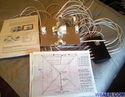
The wires above are 12-14 AWG basically speaker cables which are cut to 1/2 wavelength for each band (the area of the band you are interested in.
Ones such as the Amazon Basics Speaker Wire will do fine and might even be better then the one I used.
You will also need SO239 UHF Female Jack and you can follow the link.
I am breaking this project up into sections. I am starting with the junction box and 4:1 Balun which is housed in it. This is needed due to the impedance of the speaker cables and the 50 ohms needed to match it. So you are working with 12 Ohms x 4 which comes to 48 Ohms which is close enough. Some calculations (other hams have emailed me about this) say 14 Ohms, still close as this would only be still 56 Ohms with the 4:1 Balun.
So let's get started. The Balun is a very straight forward construction.
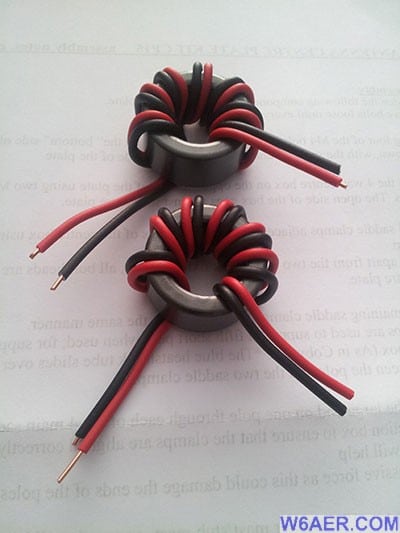
This kit I actually ordered off of ebay, here it is finished:
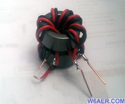
And all the parts you need. I will go over the speaker wires later as well as the frame which will support them. You will need an SO-239 plug (UHF) the balun above, a case which fits it all. Wire ties are just used to keep the speaker wires in place. Two pieces of copper as shown below. You will also need a set of four screws and nuts for the plug (Not pictured).
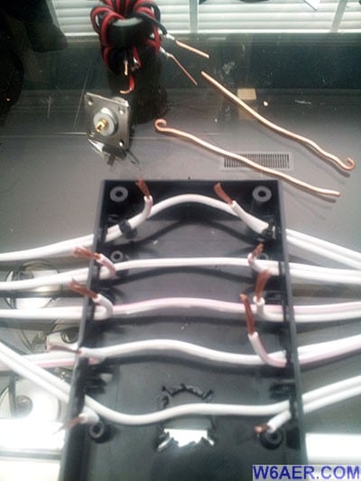
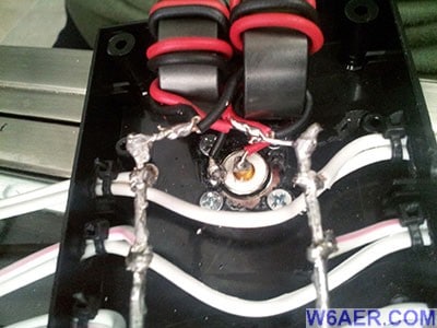
Join all connections as shown. Only one side is split on the speaker cables, more on this later. I just used a soldering iron for the cutout for the SO-239. No, I am not an artist, thanks for asking but it does the job!
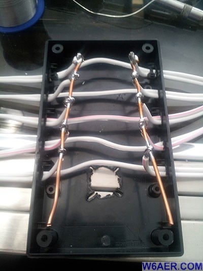
Here it is all put together (minus the cover):
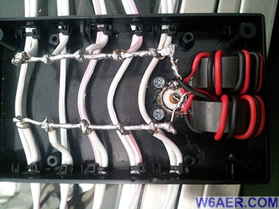
And a better angle to see how the connections are made:
Finally all closed up of the balun and junction box assembly:
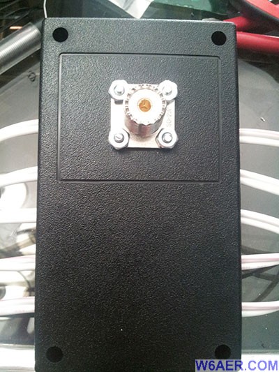
The rest consisted of simply mounting all the larger parts as seen below.
This is the bottom and the top view of the mounting plate used to hold the PVC pipes as well the connect it to the mounting post. You may recognize this as being very similar to that of the hex beam assembly.
On the left are the drilled PVC pipes with the sharpie markings I used to mark where I had measured and drilled. The wire gets fed through these.
And there is the final step of assembly. While it performed OK, I decided to stick with the hex beam and no longer use it. I am leaving this up in case someone decides to give it a shot!
If you find something incorrect, have an update, or if there is something you would like to see added to the site, drop me a line here. I like to keep things as up-to-date and as accurate as possible. Thank you! - Lucas / W6AER


