 Being the owner of the Yaesu FT-847 for mainly satellite work and as a backup HF rig, I decided to do a few modifications on the unit. First I give the SSB/CW filters a little upgrade and you can read all about that here. The next thing was to give it an IF tap so I can use an SDR and waterfall to assist in working weak signals and satellites. Obviously also useful with HF, as being a FlexRadio user I can testify to this. I selected the HupRF from Dave, G4HUP (SK) and had great results as well as great guidance from him. Sadly Dave passed on in 2017 just a year after I installed this unit. He will be greatly missed! The family appears to have taken over the business so please be sure to visit the website.
For the Yaesu FT847, we needed the 45MHz PAT50M product. For the SDR, I used a shielded (metal case) for a NooElec USB Dongle.
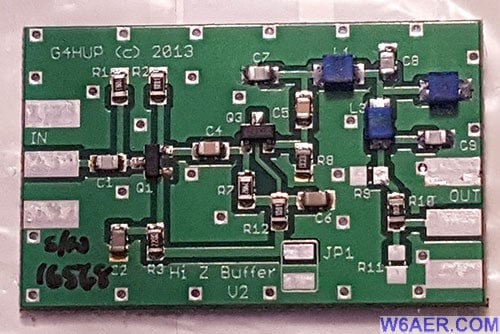
Below is the actual board you are dealing with. Very simple, add power, ground and IF in, out to SDR. Not much to it but the connections can be hard to see so I will guide you.
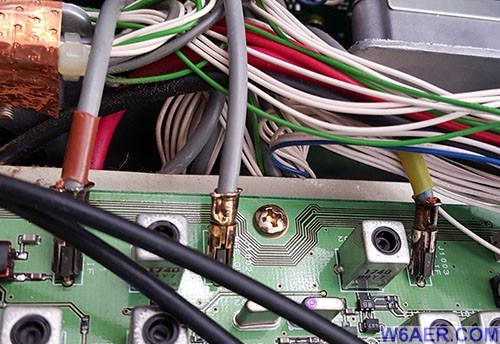
If you are like me, it is good to document the cables you unplug to make sure they get reconnected correctly. But, in case you forgot, here you go. These are the 3 cables you will likely need to move and unplug to perform the procedure. Lucky for us Yaesu color coded them! Red is left, Yellow if right, no color tape is in the center.
Power (red cable) needs to be tapped at L3102. I actually replaced the supplied red cable with something a little easier to work with and solder. Here are some views:
It basically ends up coming to the board, in my case enters from top. Black cable is bottom right and is ground. You can attach this to any common ground for negative. Note the IF in and out on the top where the coax is. It should be noted I used my OWN coax and heaver wires then it came with. Just my preference, not because they are bad.You can see the double sided tape holding the board. As you can see, it does not need to be flat, in fact I purposely made it somewhat uneven to give more distance from Yaesu circuit board.
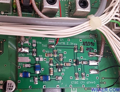
Below are two different views of how the "taps' are soldered. Note that the insulator/shield is NOT connected. Only the center conductor. You do however want to keep the shied as long and as close to the connection as possible or safe since it does keep interference out and signal in.
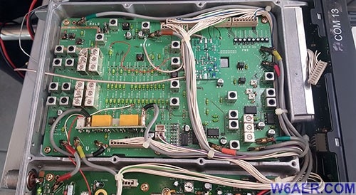
Lastly here is a birds eye view of the finished setup. Not the board in the middle top, blends in pretty well! It uses double sided, non conductive tape to hold in place as I mentioned above. This area of the circuit board is the one I found to be most suitable.
And lastly, this is how the unit looks installed in my rack mount (back view). You can see more on how it looks in the shack here if interested. The small coax coming out of the back vent hole connects to the SDR. ANY SDR will work as long as it can tune around 70MHz. This would be most! This was attached to the case with wire ties. Note the number of ferrites I used, I like to keep my signals clean coming in and going out.
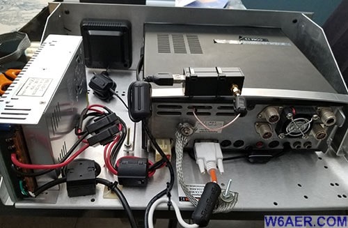
Hope this helps you and perhaps encourages you to open up your gear and improve upon it. The warranty is LONG gone on these so one less thing to worry about.
Here are the links you will need to visit to read up on this project more and/or to purchase the unit:
- SDR-Kits.net and the hufRF specific pages
- hupRF.com is where you can obtain the kit from
- NooElec is the SDR brand I used, but most any will work fine
If you find something incorrect, have an update, or if there is something you would like to see added to the site, drop me a line here. I like to keep things as up-to-date and as accurate as possible. Thank you! - Lucas / W6AER


