If you have wondered on this page, and you are the owner of the awesome Icom IC-9700 2m/70cm/23cm rig as well and want to add GPS capability....well then you are in the right place. Yes, you also can have the little satellite logo light up on your LCD and it is easier then you think. Why else should you add it? D-Star capability takes advantage of this and so on, especially if you are a rover station is very handy to have.
This project is very closely based on this article:
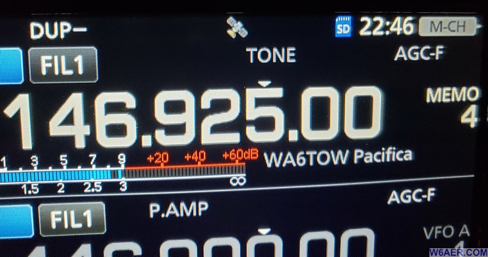
I have decided to use a metal box and for the junction (since I like to keep RF out of everything) and used all shielded cables (again...RF). I also like having an indicator that tells me if the unit is actually working! So I added the RED LED. This may have been the easiest thing I have ever built. Here is what you need:
- A GPS such as the Garmin GPS 18x which is what I used
- Enclosure - I would recommend metal especially if you are working weak signal or running power! I avoid anything plastic in the shack.
- A Cutoff USB cable, preferably one with a ferrite already on it, or add it. Use #31 (HF range) and/or #42 (VHF) I use both...paranoid!
- Data plug to fit the back of the radio, 2.5mm 3 ring jack
- LED light, resistor to match, in this case, 1K
- Zip ties to keep the cables from being pulled
- Capacitors 0.1uf Ceramic and a 47uf Electrolytic
Below is the assembled finished product:
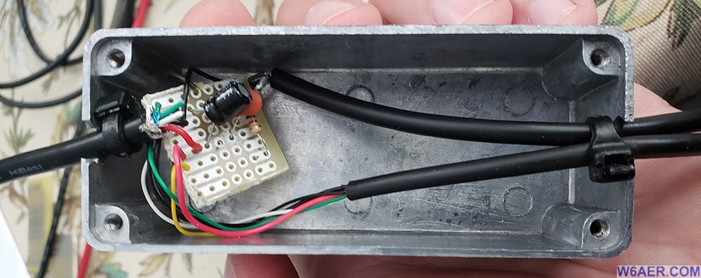
To the Icom you will run the Whiteand Green cables as these are Data in and Data out. This is for the 2.5mm Data plug in the back.
The Ground is shared. To the Red and Black are to be used on the USB cable and these are the ONLY conductors to be used on it.
Match up the Data in/out on the GPS cable as needed with the data plug for the Icom. Follow schematic on the link above.
The LED with the 1K resistor is literally just connected straight to the USB power source so I know if things are hot. The two capacitors are across the power as well, be sure to pay attention to the polarity of the electrolytic capacitor or you will hear a boom after a few seconds. They tend to rupture and pop if incorrectly fed.
That is basically all there is to it! I used an old Radio Shack cut circuit board as there really is not much needed to be soldered.
LED Side
Component Side
When Selecting a GPS to be aware that there are 3 different voltages (at least) that they come in. The most common are 5V and 12V but there is also 3V. I picked the Garmin above so I can run it from my USB hub using 5V. Be sure to Buy the 18x Model as it is newer and faster, you want the SERIAL version NOT the USB version!
In case you want to experiment with different setups I found a really good video showing some different GPS receivers which can be used: https://www.facebook.com/DXEngineering/videos/2790814757859883
Here are the Icom IC-9700 menu setting to use: Select MAIN, touch the GPS icon, then GPS set. You should see a screen like this (may change a bit with future firmware updates but likely not much.
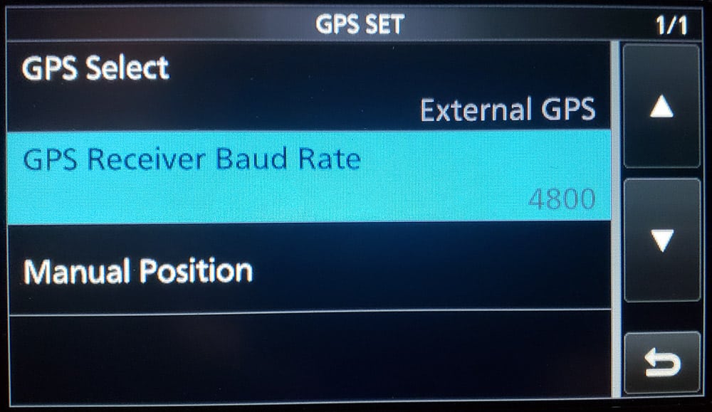
Once in there, Select EXTERNAL and then set Baud to 4800 for the above unit. The type is NEMA. Some of these might be default but check.
Lastly in the connections menu under USB (B)/DATA Functions, in DATA FunctionSelect GPS/Weather.
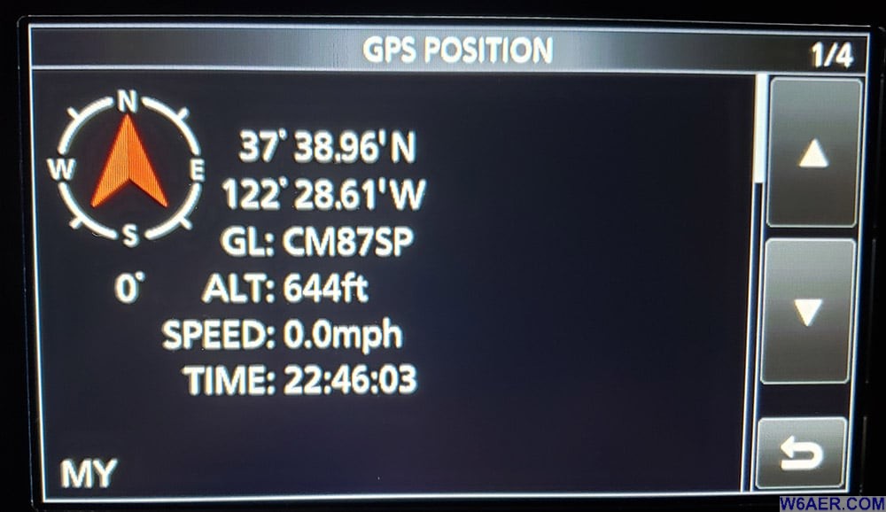
It picked up my location, elevation and 10 satellites no problem within seconds!
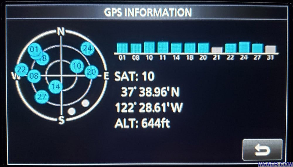
Good luck and hope you get inspired to build one as well, super easy! Thank you to the ARRL Kinks and Hints article above for the original idea for this project.
If you find something incorrect, have an update, or if there is something you would like to see added to the site, drop me a line here. I like to keep things as up-to-date and as accurate as possible. Thank you! - Lucas / W6AER


