After obtaining an older AEA PK-232MBX on ebay for under $100, I have decided to perform a major overhaul of one to bring it up to date. Basically I obtained the Eprom upgrade, DSP option (The main reason I got one), Low power upgrade, USB option (good bye serial) and the Sound Card Upgrade. While I was performing the upgrade, I did run into some things which I though I would document and share here as a suplement for those performing one or all of these upgrades or for anyone curious. In addition to the above, I also decided to install the selector switch as well as the overload light in the front panel to bring this unit up to 2013 specs.
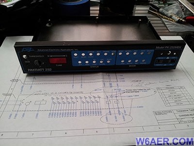
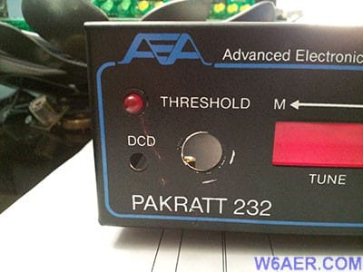
The people at Timewave were not only super helpful but also kind enought to include a schematic for me to use for the drilling I was going to perform. I used blue painters tape over the area I was going to drill to prevent damage to the case if the drill was going to slip, plus to prevent sliping and a sharpie to mark it. I would recommend starting with a smaller drill bit and work your way up. Please see images below to see final results. Here it is Before:
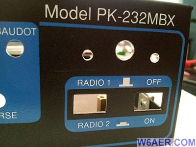
And After:
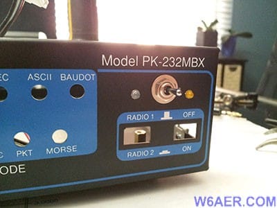
And the other side Before:
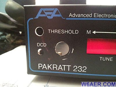
And After...The only new thing is the red LED which connects directly to the DSP board (not documented, watch Polarity!) also note the sleeve around the LED. Both Parts available at your favorite Electronics store:
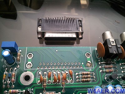
This concludes the Mechanical Modifications required. Now on to the Electronic portion. The First think I would recommend is if you had purchased the USB upgrade, remove the 25pin serial connector (AKA RS-232). Don't do what I did, burn the solder if you can avoid it. You will need a solder sucker and a lot of patients as well as a high wattage soldering iron, I used a 125W but you can do it with a 50W-75W and more time. The pins are easy but the 4 supports (2 per side) are a bit nasty.
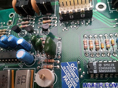
The Upgrade requires you to remove some of the components. These are a quite a challenge to find since the silk screening is UNDERNEATH the components. So hopefully the photos I took will help you speed up the process of finding the parts to clip out. Here is the resistor R28.
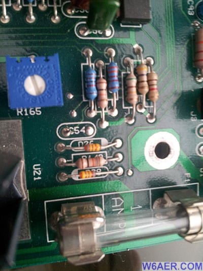
And the Capacitor C54: (This one took me 15 minutes to locate)
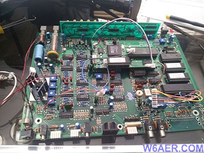
After getting the Eprom and DSP installed, it should look like this:
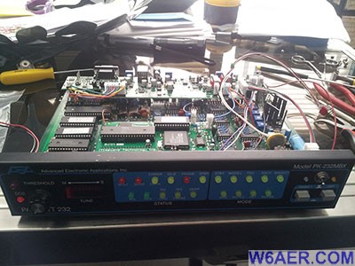
And here is the completed project:
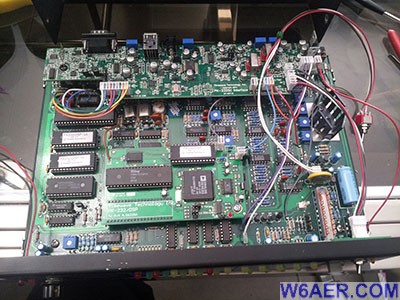
And from the top. The only thing not connected is the front overload LED which connects right next to the red LED you see on the DSP board (Aprox. Middle of Photo) Be sure not to reverse this. It blinks on bootup so this is a good time to test it. I would recommend doing this additional modification.
In Conclusion, I would highly recommend doing this upgrade as I did it, it is if you have the time (3 hours) and interest...And Money. Not cheap but worth it. If you have any questions, please feel free to shoot me a line!
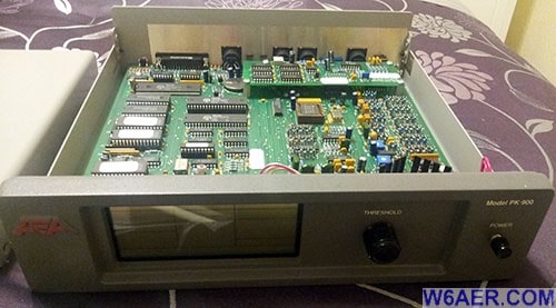
As a little extra bonus, I happen to have some photos of the AEA Timewave PK-900 when I opened it up. I never did any modifications or upgrades on this unit but it was nice to play around with for a while. This was in 2014 or so. For those who might be curious about this unit, here you go:
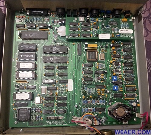
Hope you got something out of this little write-up. 73 for now!
If you find something incorrect, have an update, or if there is something you would like to see added to the site, drop me a line here. I like to keep things as up-to-date and as accurate as possible. Thank you! - Lucas / W6AER


