This project all started due to my need to switch multiple transverters on my flex radio. A transverter, for those who may not be familiar with them is a device that allows a radio to use frequencies outside of it's operating range. For example, 2m transverter can be made to receive (and transmit) on the 10m band setting of a controlling radio. Very common on VHF/UHF as well as sometimes now the new 630m and 2200m bands transverters are designed to use the control radios 160m band...most of the time at least.

I will not cover the circuit board as this is something that can be purchased directly from the W6PQL website for about $100. The project involves finding a creative way of wiring it up based on my needs as well as likely other FlexRadio users.
The Unit was mounted in an old Blackbox Rack mountable serial switch box. It was perfect and even allowed me to keep the switch and reuse it for the 3 manual selections as well as to put it into auto mode which reads and selects based on band data.
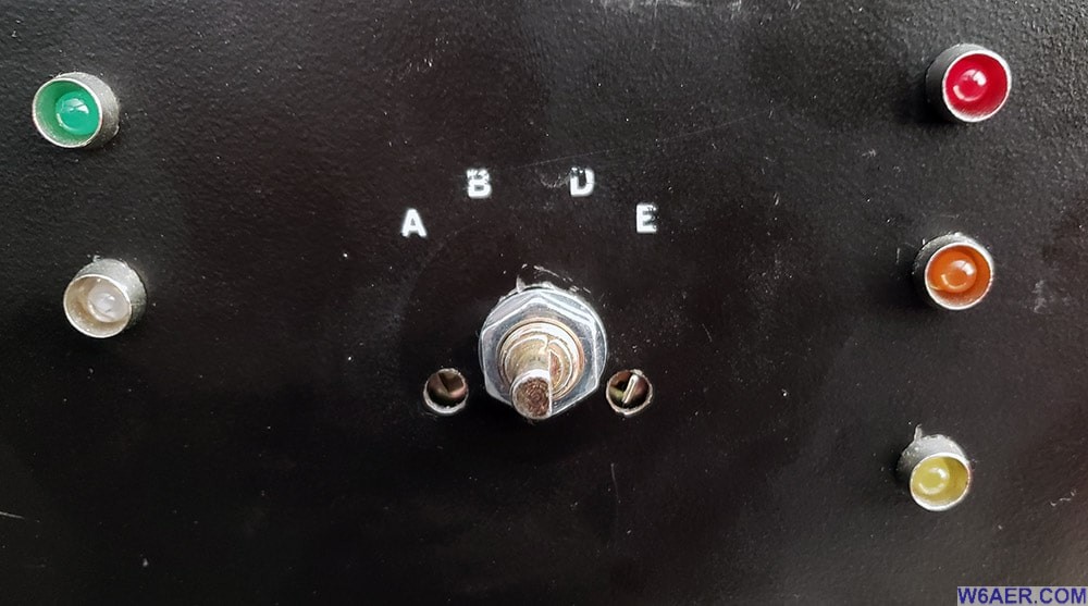
To make it easier to ID the selected band in low light, I used different color LEDs. Green is AUTO which is based on band data coming from the radio, red, orange and yellow are the 1,2 and 3 manual selectors in case it is in over-ride mode.
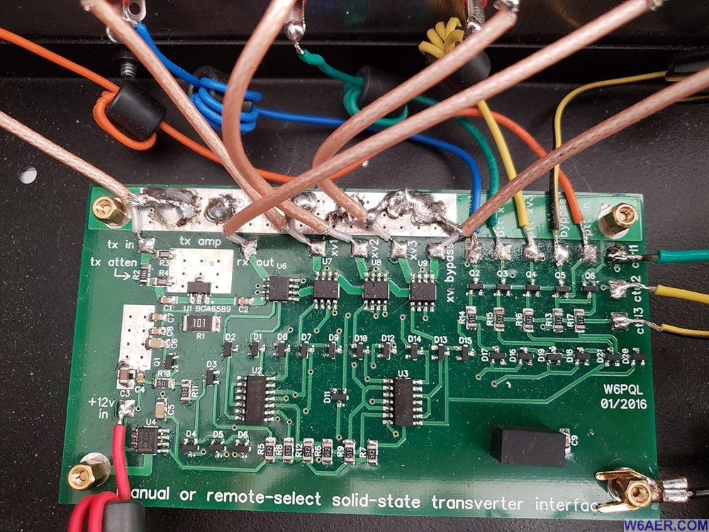
Below is the actual board with all the wiring completed per the instructions from the designer. You will need to purchase a few minor things to complete it, such as some ferrites, risers to mount the board, LEDs, various wiring. Additionally BNC, RCA and power plug. BNC is for IF, RCA is for PTT.
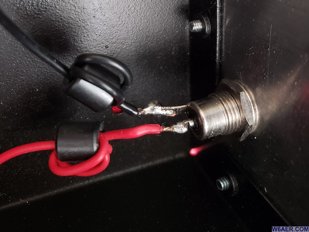
An inside view of the the power and front power wiring. Be very careful to use medium to low heat for soldering the BNC to the Coax as to not melt or othervise damage the cables.
I had left over ferrites from my order so I installed a couple of extras over the power cables.
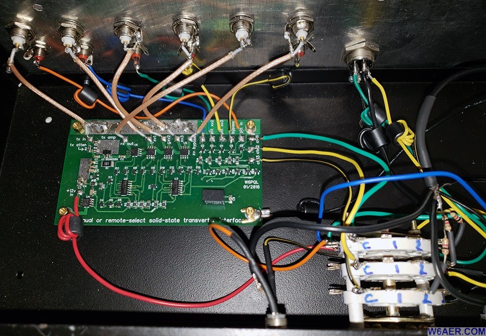
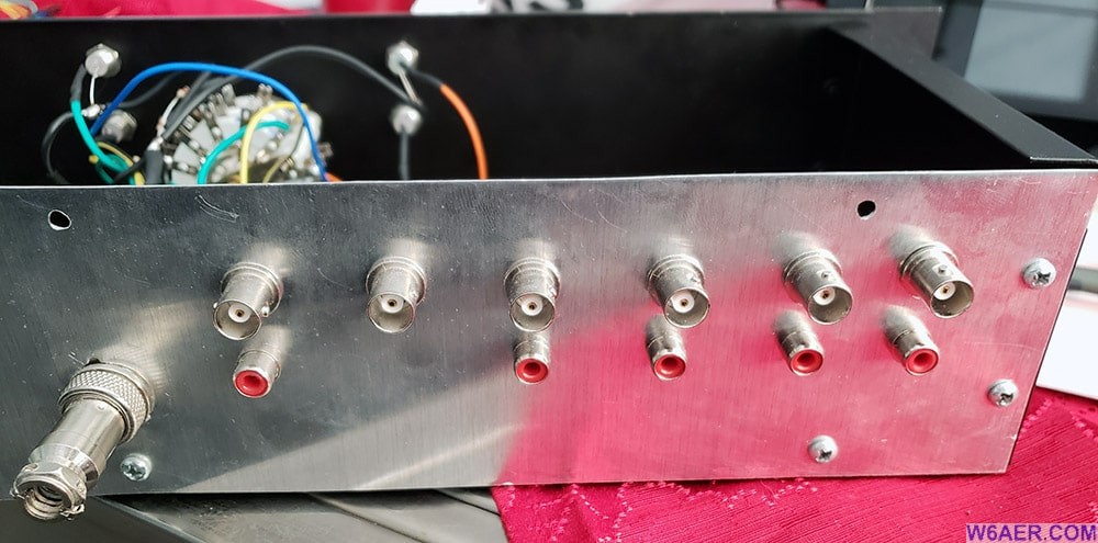
Here is a wide angle view of the guts with all the goodies wired up. The connectors are BNC and are common IF (not separate RX and TX). the corresponding RCA jacks are the PTT to go along with the corresponding selection. The metal back panel provides a common ground.
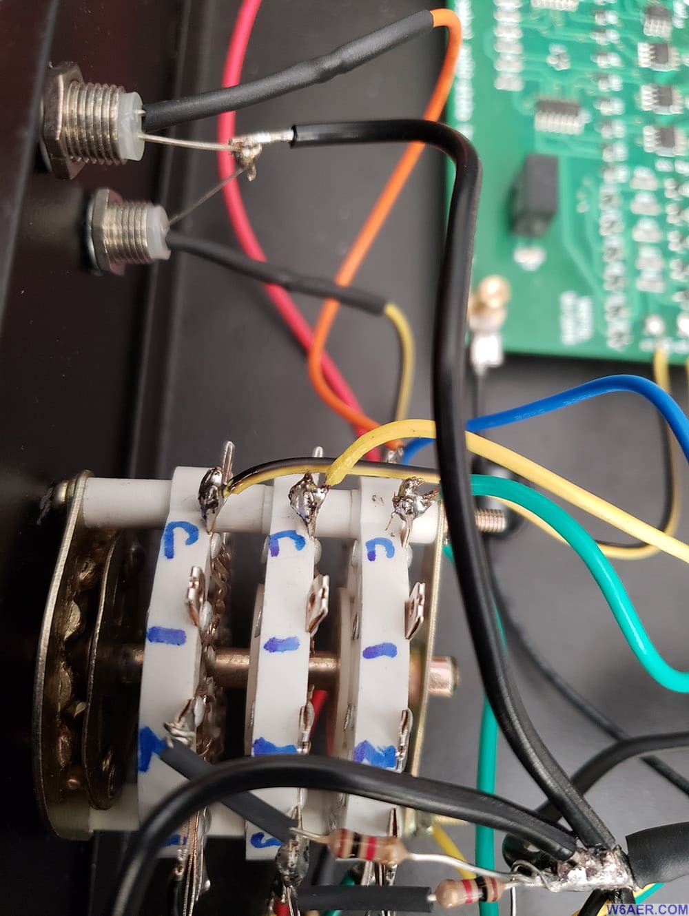
Below is a closeup of the rotary switch, I do recommend figuring out the pinout with an ohm meter and labeling it. Will save you a lot of grief! Note how I used many different color cables to make it easier to trace. The only standard colors I used were the usual black and red for power. All others were of a different color.
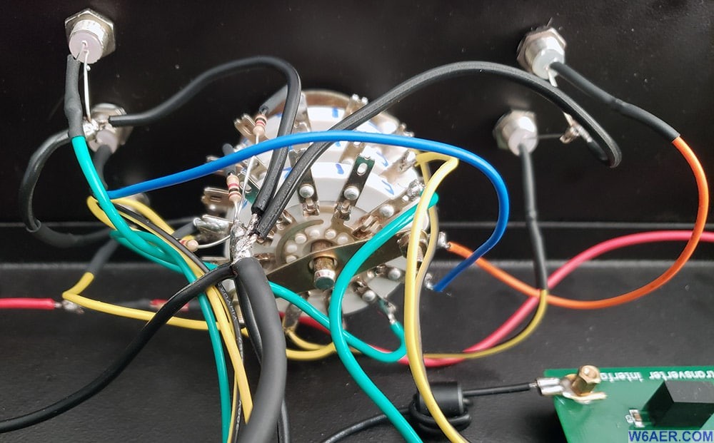
Here is the side view of the final wiring. Not all terminals needed to be used for the rotary dial selector.
This is the rear view. The back panel was cut out from a piece of sheet metal and drilled to mount the BNC and other connectors. Provides a nice RF shield and looks fairly professional.
I am very pleased with the final product. I have seen these mounted in many different boxes, however I do recommend using a metal enclosure. If you made this as well, send over some photos or a link to where you have it posted so others can get inspired with some good alternative ideas.
If you find something incorrect, have an update, or if there is something you would like to see added to the site, drop me a line here. I like to keep things as up-to-date and as accurate as possible. Thank you! - Lucas / W6AER

